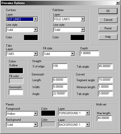
The Dioramas Options command allows you to set the defaults used when drawing CCD models. To call up the Dioramas Options dialog box, click on the Dioramas Options icon ![]() :
:

Layer allows you to select the default layer onto which cut lines will be drawn. For standard CCD drawings, it is not necessary to change this entry.
Line style will change the current line style that will be used by new cut line entities.
Click on the Color box to bring up the standard CC3 color dialog to select a color for new cut line entities.
Layer allows you to select the default layer onto which fold lines will be drawn. For standard CCD drawings, it is not necessary to change this entry.
Line style will change the current line style that will be used by new fold line entities.
Click on the Color box to bring up the standard CC3 color dialog to select a color for new fold line entities.
Layer sets the default layer onto which glue tab entities will be drawn. For standard CCD drawings, it is not necessary to change this entry.
Fill Style will change the current default fill style for glue tab entities.
Depth will change the current default depth (width) of glue tab entities.
Clicking on the Colors boxes will bring up the standard CC3 color dialog, allowing you to select the color used for tab outlines, fills, and the non-tab portions of geomorph plug-in tabs.
For tabs to be drawn along Straight edges, you can change the default percentage of the edge selected across which to add a tab, and the angle to which the tab entity inclines at its edges.
For Geomorph plug-in tabs, you can set the default base width of the tabs drawn (CCD will draw multiple tabs of this length if the edge selected along which to add geomorph tabs exceeds this value by a factor of 2× or greater), the length of the geomorph tabs drawn not inclusive of their glue tabs, and the angle to which the geomorph tabs will incline towards the center top panel of the tab.
For tabs to be drawn around Curved edges, you can set the default segment angle, the minimum length of the glue tabs to be drawn, and the angle at which the tabs incline from their base to their apex. The default segment angle determines the angles at which tabs will be drawn (i.e., setting this value to 15 will default to drawing one tab along a curved edge every 15°). However, since drawing tabs around a small curved edge may produce unmanageably small glue tabs, you may set a minimum tab length. Thus, the total number of glue tabs drawn will depend on the default segment angle, the minimum tab length, and the length of the curved edge selected.
Foreground changes the current default fill style used for panel foregrounds. This should normally be set to either a symbol fill style, or Hollow.
Background changes the current default fill style used for panel backgrounds. This should normally use a bitmap fill style, or Solid.
There is separate Color box for both foreground and background. Click on these boxes to bring up the standard CC3 color dialog box, allowing you to pick the color you wish to use for the panel component in question. Note that changing the color of a panel component using a bitmap fill style will not, visually, alter that component. However, it is good practice to set a color for such entities, since commands such as selecting by color will recognize this setting.
There is a separate Layer setting for both foreground and background. These are used to select the layer onto which the foreground and background components of a panel are to be drawn. For most CCD drawings, these should not be changed.
Since wall sections beyond a certain length will not fit into the standard CCD template drawing sheets, you can set the Max Length used to calculate multi-wall nets to limit the length of nets drawn by the Multi-Wall Net command.
Only change the default layer settings if this is absolutely necessary to achieve the drawing you desire.
Changing the Tabs options is useful if you wish to alter the maximum number of tabs that can be drawn using the Add Tab key along a given entity, or for situations where the standard tab options will draw tabs that overlap part of your drawing (e.g., you may require a more acute tab angle to avoid overlaps in complex or intricate drawings).
Changing options in this dialog box will not affect those entities already drawn. For example, if you have already drawn fold lines using a default line style of Solid, changing the default fold line style using the Dioramas Options command to Road will not change the previously drawn fold lines to that style. It is thus desirable to set the options you require for a given drawing before you begin.
The options you set will carry over to new CCD drawings. If you wish to use a specific set of defaults for your CCD drawings, you need not change the defaults for every drawing you create.
Text Equivalent: TABOPT
Related Topics: