On the Symbol menu click Add Control Points.
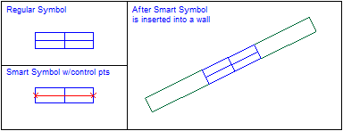
Control points are added to regular symbols to create "smart symbols". Control points are only included in symbol definitions. Smart symbols work intelligently with other straight-edged CC3 entities in that both the symbol and the entity are aware of each other during insertion. This awareness allows the entity to automatically create cuts to accommodate the symbol, or have the symbol align or scale itself to fit cleanly. Typical uses for smart symbols would be doors, windows, etc.
Entity type |
Effect on smart symbols |
|
Lines, paths, boxes, networks, polygons |
Aligns and cuts |
|
Arcs, smooth paths, smooth polygons |
Aligns and cuts, but cuts are not necessarily entirely accurate |
|
Symbol references |
Aligns, doesn’t cut. |
|
Multipolies |
Ignores |

Note that control points are invisible after a symbol is inserted.
Control points are added to symbols before they are defined. When creating new symbols, just add control points as an entity and be sure to include them when you select entities during the DEFINE SYMBOL phase. If you are working with existing symbols, you can use the EDIT SYMBOL DEFINTION command to add control points. Use the EDIT command to change existing control point options.
Control points are usually placed from left to right with the Origin in the center. Symbols that abut an outside wall should have the control points placed from right. It is easier to place these control points if Snap & Csr Snap are turned off
You can force control points to cut only on their current layer, by setting the Symbol Options for the symbol to include control points cut only on same layer.
A symbol definition can only contain one pair of valid control points.
The prompt reads "1st point:" and then "Next point:". The positioning of these two points is important.
Firstly, the two points define a vector that is used to determine smart symbol alignment with other entities. During placement, this vector remains parallel to the entity, reorienting the symbol accordingly. This allows a single smart symbol to be used for entities along any bearing! The alignment vector also tells CC3 how to "flip" the smart symbol during insertion.
The two control points also define the entity "cut points" when the symbol is inserted into an entity. The smart symbol will cut the wall just as the WALL CUT command would. The wall cuts are capped perpendicular to the span direction.
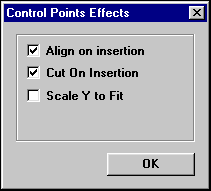
Control points are necessary for any smart symbol, but you can switch on/off their ability to align or cut upon insertion using the Control Points Effects dialog. This dialog appears automatically after you draw the two control points.

Align on Insertion
Enable this option to auto-rotate the reference upon insertion. The smart symbol will only align when placed on a linear entity. The two control points define the direction of the smart symbol alignment.
Cut on Insertion
Enable this option to automatically break the existing linear entity to accommodate the smart symbol. The break will occur at the control points.
Scale Y to Fit
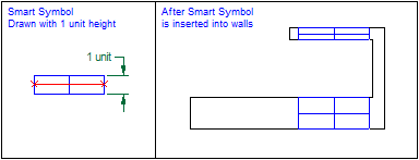
Enable this option to force the smart symbol to resize in the "vertical" direction upon placement. This resizing is relative to the width of the wall into which the smart symbol is inserted. This option only takes effect when inserting into entities with width > 0.
You can define a smart symbol so that it automatically snaps to the same width as any entity. To do this, the ends of the symbol that abut the wall cut (where the control points go) must be one unit long. Symbols constructed with Scale Y to Fit will scale in the Y-direction only. The length in the X-direction (the vector defined by the control points) remains constant. This can cause circular entities to distort into ellipses upon insertion.

Keep DynTrack Scale
If checked, causes symbol to honor dynamic scaling/rotation performed during insertion into linear entities. Hold down the CTRL key during insertion to dynamically scale. If unchecked, the symbol will insert using its defined size. Leave this option unchecked to "lock" insertion size and alignment into linear entities.
Offset from Place Point
Enable to insert the symbol parallel to the initial placement point and orientation. The exact placement is visually determined from the dynamic cursor. This overrides the Cut on Insertion check box option (i.e., offset symbols will not cut the locating entity). This is used, for example, to allow houses to be offset from roads.
Text equivalent: CTRLP
Related Topics
creating frill symbols
Creating building symbols ![]() Go to the Symbols overview
Go to the Symbols overview
DEFINE SYMBOL command