Connecting Symbols
|

|
Connecting symbols are collections of symbols which combine to create roads, corridors, hedges and other networks. They can make turns, have special corner and end pieces. can spot connecting symbols in the symbol catalog window because they have a C in their symbol window.
Where appropriate, there are end pieces and "join" junction symbols before or after the connecting symbol in the catalog. For example, after the access tube pictured left is a selection of endpieces and crossroads, Click the + sign to see them all. |
Using connecting symbols
This is very straightforward; just select one then click points. Depending on the connecting symbols available, you might be able to turn corners at fixed angle, or any angle at all.
Creating connecting symbols
If you're interested in creating connecting symbols, read this then set to work creating a catalog. Start really simple, and slowly add complexity. You'll be amazed at what you can create.
Getting Started
-
Start a new blank drawing.
-
Draw each symbol in drawing, with its origin on a grid point, to be defined later.
Naming the symbols
Straight symbols are named with the symbol’s root name followed by a number in sequence (e.g. "symbol 1", "symbol 2", etc). Important – even if there’s only one straight symbol, the number must be present. Sometimes the length is included in the name (more below)
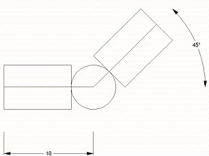
Bend symbols are named to include the angle of bend and the length of the bend arm within square brackets, each value separated by a colon. If there’s more than one symbol for the same angle and length, a number goes after the brackets. The bend angle is measured anticlockwise from 3 o’clock. The following symbol could be named "dash dot [45:10]":

If there were two similar symbols, they would be "dash dot [45:10] 1" and "dash dot [45:10] 2".
Setting the Connecting Symbol flag
After you have drawn each symbol, before you close the symbol definition window, click Symbols >> Symbol Options. Check the Symbol is a Connecting Symbol tick box.
Symbol origin
Symbols flow from left to right. For straight symbols, the symbol origin is the leftmost point (normally the midpoint of the left hand edge).

For bend symbols, the symbol origin is the center of the angle.
Symbol length
Unless the length is included in the symbol name, CC3 finds the length of a straight symbol from its x extents (its maximum horizontal width).
There must be a straight symbol with a length equal to the shortest bend length. So, for our dash dot symbol, there must be a straight symbol length 10. If this symbol is missing, the usual symptom is that the first and last segments do not draw.
If bend symbols have different arm lengths, there must also be straight symbols equal to each difference in length. So, if you have bend lengths of 2.5 and 3.25 (a very bad idea), you’d need straight lengths 2.5 and 0.75.
Other symbol lengths are optional, but knowing how CC3 chooses and uses symbol lengths is useful to creating efficient symbol sets:
CC3 uses a variant of the Greedy algorithm for choosing symbols. At each choice, it picks the longest symbol that will fit. By defining symbol collections carefully you can give them the Greedy Choice property, which means the first choice will always be the most efficient. By choosing lengths badly you can give CC3 a much harder time. It will still cope, but will use a lot more symbols.
An example of building a straight section using a Greedy Choice set of symbols:
If you created a set with lengths 100, 50, 20, 10, 5, 2 and 1 it would be efficient. The shortest length defines the cursor snap. In this case it will be 1.
When you click points to make a straight, at each choice CC3 picks the longest symbol that will fit. A 196 straight would use 100 + 50 + 20 + 20 + 5 + 1. This is the most efficient possible choice. CC2-Pro then randomizes the order in which symbols are used, so this example may come out: 5 + 50 + 100 + 20 + 1 + 20.
An example of building a straight section using a Bad Choice set of symbols:
A Bad Choice set may be necessary for other design considerations, such as pipe bends that have to be 2.5 long to fit a corridor. In a Bad Choice set, the greedy choice might not work first time around. If this happens, CC3 goes back removing big pieces until a smaller one can be placed. For example, if you had a tube catalog with pieces 5, 2.5 and 1 long, and you draw a length of 14 the algorithm will:
-
Take 5 (rest is 9)
-
Take 5 (rest is 4)
-
Take 2.5 (rest is 1.5)
-
Take 1 (rest is 0.5 – doesn’t work)
-
Remove 5 (rest is 5.5)
-
Take 2.5 (rest is 3)
-
Take 2.5 (rest is 0.5 – doesn’t work)
-
Remove 5 (rest is 5.5)
-
Take 2.5 (rest is 3)
-
Take 2.5 (rest is 0.5 – doesn’t work)
-
Remove 2.5 (rest is 3)
-
Take 1 (rest is 2)
-
Take 1 (rest is 1)
-
Take 1 (rest is 0 - hurray)
You get 2.5+2.5+2.5+2.5+1+1+1+1
Notice that the result is much shorter lengths, and not as efficient as it could be. In a future update we will improve the efficiency here.
Drawing a straight symbol with a seamless connection
Some symbols, e.g. a railway track, need to join seamlessly. For this to happen, the rails must meet each edge of the symbol at the same vertical (y) point. The easiest way to draw precisely is to use the grid and CC3’s precision drawing tools.
-
Pick a garish color, such as purple (color #7) and draw a construction line from (0,0) to the desired symbol width, e.g. @10,0.
-
Draw a construction line, midpoint (0,0), for the left hand edge of the symbol.
-
Use construction lines to mark the position on the left-hand edge of any features that connect from symbol to symbol.

-
Create the right hand edge by mirror copying the left hand edge (complete with construction lines). The mirror line is a vertical line, starting at the midpoint of the symbol width. Use Ortho to easily make the mirror vertical.

-
Add the detail. Provided it meets each edge at the same vertical point then, no matter how complicated the detail is, the symbol will connect seamlessly.

Drawing a bend symbol with a seamless connection
As with straight symbols, the key to getting this right is good construction lines and mirroring the edges so they connect correctly.
-
Draw a construction line from (0,0) to the left-hand edge of the symbol, e.g. @ -10,0 (that’s @ minus 10, 0).
-
Draw a construction line for the left hand edge of the symbol.
-
Use construction lines to mark the position on the left-hand edge of any features that connect from symbol to symbol.
-
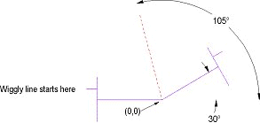
Create the right hand side by mirror copying the left side with a mirror line that bisects the angle. The bisecting angle is simply 90 + half the bend angle. So, for a 30 degree bend, this is 90 + 15 = 105 degrees. To input this mirror line, type 0,0 for the first point, then <105,10 for the second. (< is CC2-Pro’s notation to say "an angle and length follows". In the case of a mirror line, the length is unimportant provided it is not zero. 10 just trips off the fingers).

-
If the symbol is for a smooth curve section, e.g. a road or a railway, it is usually better for the curve to encompass the whole symbol. This allows different bend angles to join smoothly. To draw these curves accurately you need to know its center. Find the center from the intersection of the two end pieces. Mark this point with a circle so you can easily snap to it (F4 is snap to center point).
-

-
To draw the arcs, right-click the arc icon and choose the Center, Start and End method. Draw anticlockwise.
Variable bend angles
If a symbol set has no bends defined, it is assumed that it can bend by any angle at any node. An example would be telegraph wires, where the wire goes from pole to pole, and can bend any amount at any pole. So the simplest connecting set could be "Telegraph 1".
It is also possible to define a bend symbol that works at any angle. An example use would be a castle tower, where the castle walls can join the tower at any angle. These are named: Symbol Name[*:length]. The * indicates any angle, the length can be 0 or greater. A 20’ radius tower, for example, could be Tower[*:20].
You can combine variable and fixed angle symbols in the same set. If the tower set included Tower[90:20], and you drew a bend exactly 90 degrees (e.g. via the grid), the [90:20] symbol would be used. If your bend was 90.5 degrees, the [*:20] symbol would be used.
Completing the symbol
It's normally a good idea to draw the entire connecting set of symbols side-by-side. This allows you to copy and reuse existing detail easily and to check for correct tiling, color matching, etc. Once the set is complete:
-
Erase any construction lines
-
For each symbol use Define Symbol from the Symbols menu.
-
Type the symbol name (using the rules above), pick the symbol origin (mid-left edge of a straight symbol or the bend point of a bend symbol), and finally pick the entities for the symbol.
-
Click Symbols >> Symbol Manager.
-
Cick Edit and pick points for an edit window.
-
Click Symbol Options… from the Symbols menu and select the options Symbol is one of a collection and Symbol is a connecting symbol. Do not select Randomly select from collection as this interferes with CC2-Pro's calculations to decide which symbol to use.
Gaps and Overlaps
If you want a gap between symbols, you have to fake the width of the symbol to be greater than it actually is. There are two ways to do this:
-
You can add (non-drawing) control points to the desired width with no options set.
-
You can force the symbol width by adding it to the symbol name in square brackets. An example name using forced length is: TestSym[70]4. You can then draw the symbol however you like (wider than 70, and / or using negative x values), and it will insert as if it is 70 wide.
If you want overlapping symbols, i.e. where the second symbol starts before the end of the first, you have to use option 2, the named width.


